Shaders
Common Shaders:
Geometry -> Vertex -> Fragment
- Geometry Shaders
Geometry shader programs are executed after vertex shaders. They take as input a whole primitive, possibly with adjacency information. For example, when operating on triangles, the three vertices are the geometry shader’s input. The shader can then emit zero or more primitives, which are rasterized and their fragments ultimately passed to a pixel shader.
- Vertex Shaders
Runs once per vertex given to the graphics processor. Transforms each vertex’s 3D position in virtual space to the 2D coordinate on the screen (as well as a depth value for the Z-buffer). Can manipulate position, colour and texture coordinates, but cannot create new vertices.
- Fragment Shaders/Pixel Shaders
Computes colour and other attributes of each fragment. They can alter the depth of the fragment , or output more than one colour. A pixel shader alone cannot produce some kinds of complex effects because it operates only on a single fragment, without knowledge of a scene’s geometry. However, pixel shaders do have knowledge of the screen coordinate being drawn, and can sample the screen and nearby pixels if the contents of the entire screen are passed as a texture to the shader.
Fragment Shaders
Colours
Flat Colours
- gl_FragColor = vec4(R,G,B,A);
- Normalized: Values from 0-1.0.
- Use floats. Integers might cause issues.
- precision lowp/mediump/highp float;
- Precision affects performance. Lower is better.
Uniforms
- Resolution
- Mouse
- Time – Can be used in tandem with Math functions.
Varying
- gl_FragCoord – screen coordinates of the pixel

Step & Smoothstep
- step( edge , value to check )
Returns 0 before edge threshold. Returns 1 after the edge threshold.
- smoothstep( start , end , interpolation value )

vec2 st = gl_FragCoord.xy/u_resolution;
	gl_FragColor = vec4(st.x,st.y,0.0,1.0);
The first line normalizes the resolution into coordinate values from 0 to 1. The above example demonstrates a gradient from green to red starting from the top left (0,1) to the bottom right (1,0).
Shapes
- Rectangle – Normalize the coordinates (coord/resolution). Use a stepping value to define edges. Multiply left and bottom (Acts as an AND operator). Invert coordinates for top and right. Render colour.
- Circle – Find distance to the centre(0.5 coord). Map as a colour. Set to get darker the closer to the centre it gets. Can use step to harden edges. eg. step (radius, distance to centre).
Houdini
Log of findings/techniques from Houdini tutorials. Practice is focused on creating a procedural HDA file with controllable parameters.
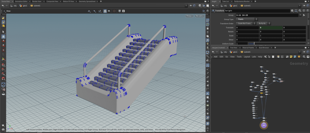
Procedural Stairs
Use of nodes to retrieve desired points and primitives to then manipulate with parameters. Points and primitives can be grouped to have attributes changed. Use of the transform node to achieve more specific point transforms to later be added as a parameter in a subnet/HDA.
Procedural Bridge
Use of noise on pscale to create procedural bevels. Chain node to chain together different primitives.
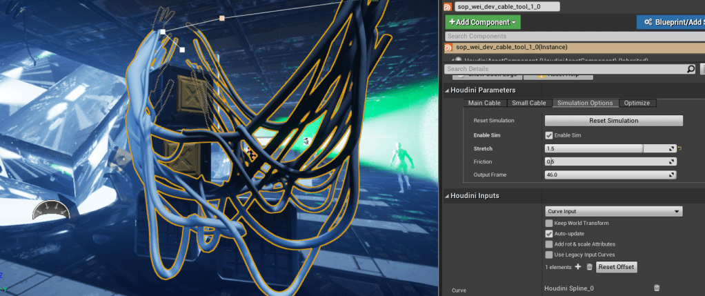
Procedural Cables
Use of vellum and timeshift to simulate cables in Unreal Engine w/ Houdini Engine.

Maths & Tech
Maths
Dot Product : Angle Between Vectors (eg: Lighting, AI View Angle)
Cross Product : 90 degree, Perpendicular Vector Between 2 Vectors (eg: Calculation of Normal, Collisions)
Tech
Forward Rendering : No Render Passes
Deferred Rendering : With Render Passes. Lowers Fragment Count. Calculates Lighting on Pixels. Uses Resolution Size instead of Fragment Count.
SDFs and Ray Marching : Blends with algorithmic meshes.
